|
|
Bob's Shop Notes: |
|
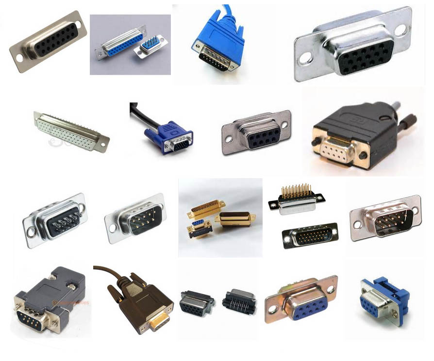
Click here for larger image. The D-Subminiature (D-Sub for short) connectors are probably the most cost effective wire interconnection products on the planet. They're everywhere. The back of your computer is populated with them. Industrial and aeromotive electronics designers are known to use them. They are my personal 'connector of first consideration' when designing a new product. There are versions manufactured to military and space-grade qualifications. Check out MIL-C-24308 on the 'net. Given that they're manufactured in such high volumes, D-Subs for more mundane applications are available at very attractive prices. There are hundreds of configurations offered with pin counts ranging from 9 to 50 for 20AWG wire. Specialized versions are also offered with fat-wire pins and pins designed to carry coaxial cable feeders through the connector. Hi-Density and Micro-D versions offer high-density 22AWG pins still greater wire counts in a small space.
|
|

|
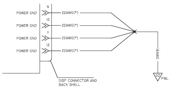
Click here for larger image. The down-side of 20AWG D-Subs is the current carrying ability of a single pin is limited to 5 Amps. This article features a process for carrying higher than rated currents through the standard density connectors. Individual pins in a 20AWG D-sub are rated at 5 Amps each and an interface resistance of 2.7 milliohms maximum. The design goal is to force paralleled pins to SHARE the total current as uniformly as possible. Let's say we paralleled 3 pins together with a notion of loading the array carry 12 amps. While the male/female pin interfaces are rated at 2.7 mOhms max, we cannot count on all three pins having the same resistance. Hence, the only way to be sure that the pins share the total current equally is to put some form of ballasting resistance in SERIES with each mated pare BEFORE it is paralleled with other pins in the array. Suppose we want to use a D-Sub as a wing root wire bundle connector with a 100 watt landing light and 12 Amps pitot heater in the wing? Connector breaks mid-harness require pins to be connected in parallel on both connectors. In this instance, we'll want to use 6" pigtails of 22AWG wire in each pin joined to the single wire with solder or a butt splice. The schematic of this interface looks like this . . . When bringing multiple wires together for connection to the main run of wire, I've demonstrated that four, 22AWG wires will fit into red (18-22AWG) PIDG terminals and splices; 5 to 7 wires can be crimped into a blue (14-16AWG) PIDG. CLICK HERE for a comic book on the technique. |
|
Click here for larger image. There are some instances where your greater-than-5A current path plugs into a connector were there are no ballasting resistors associated with the paralleled pins. No problem, just put full 12" pigtails on the harness side. A quick note on the 'pigtails'. 22AWG wire has a nominal resistance of 16 mOhms per foot. The individual pins are something like 2 plus or minus 1 mOhm. That percentage of variability makes accurate interconnection and load sharing problematic. By adding the 15 mOhm 'resistor' in series with each pin makes our new path resitance 17 plus or minus 1 mOhm. The additional fixed resistance inserted with the pigtails reduces pin-to-pin resistance variations to insignificant. Examples of this instance include bringing greater-than-5A conductors to the instrument panel ground bus as illustrated in Figure Z-15 of the 'Connection. Other examples will included AeroElectric Connection accessories that control higher currents though D-Sub connectors. |
|
Click here for larger image. I first introduced this concept to a military customer of Beech Aircraft's Targets Division in a design review meeting. The skepticism was palpable. The first question asked was "How will you know if one of the paralleled pathways has failed? Wont that cause a new sharing of the current at higher levels per pin?" Of course the answer was, "Yes". The counter question was, "What is the reliability level assigned to mil-spec pins in a connector? "We have numerous instances all over the Target where a single pin failure puts the vehicle at risk. Yet for all practical purposes, properly installed and mated connectors are considered to have 10 to the minus 9 (or better) failures per flight hour and are generally not part of our reliability studies. I'll suggest that any single pin in an array of paralleled and ballasted pins in a high current path through the connector is no less reliable." |

|
|
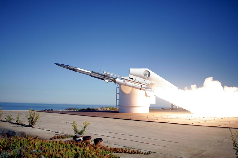
Click here for video (CAUTION - 28M File). Some months after the picture above was taken in the EMC Lab, first flight of the GQM-163 carried the power distribution box through a 30G launch and Many-Mach ride over the Pacific Ocean. 25 Amp power paths within this vehicle were carried on arrays of 7 paralleled and ballasted pins in D-Sub connectors. This is one excellent example of elegant design. The legacy power distribution boxes for decades of target production were much larger, used mil-spec, hermetic relays (expensive) and Mil-C-38999 connectors (also expensive). Use of ECB mounted D-subs and solid state switches reduced the cost of the power distribution and control box went down by a factor of 10, the volume dropped by a factor of 20. Pretty good deal considering that this vehicle hits the ocean every time. Bottom line for this design philosophy suggests that if it's good enough for the U.S. Navy, it's probably just fine in your RV-7.
|