

|
The "firewall" on an airplane wasn't named with any sense of
whimsy . . . 99.99% of the time, all it does is keep a blast of cold air out of
the cockpit. But on rare occasions, it is expected to stand between a fuel
fed fire and folks in the cockpit who are doing their best to survive
the experience.
Hundreds of thousands of single engine aircraft have been built in the past
100 years. Most were fabricated with some attention paid to the physics
of fire protection. Every firewall-sheet of stainless steel (or composite
material selected for it's fire resistance) is perfectly capable
of doing its job . . . as long as you don't cut holes in it. Unfortunately,
it's necessary for things forward of the firewall to be in communication with
things aft of the firewall. There are controls, fuel plumbing, instrumentation
and power generation wiring that must run between engine compartment and cockpit thus
requiring a certain number of HOLES in the firewall.
Penetrations of fuel and other fluid plumbing running through all
metal bulkhead fittings require little further consideration. For certified
airplanes, the FARs tell us that bulkhead feed through fittings of
steel or copper-alloy may be used with no concerns for compromising firewall
integrity. There are a variety of metal "eyeball"
fittings available for easing the transition of throttle, prop, mixture and
cowl flap controls at odd angles. This leaves us with the "soft" lines such
as wires and perhaps small fluid lines for pressure instrumentation.
|
Click here for larger image A visit with
camera in hand to a production line for certified piston aircraft allowed me
to record and share a fabrication technique for soft penetration. This technique
has a long history of laboratory testing for effectiveness, production line
convenience, and field maintainability. In this case, all of the wiring comes
through a single, fairly large penetration fitting . . . but there's no reason why
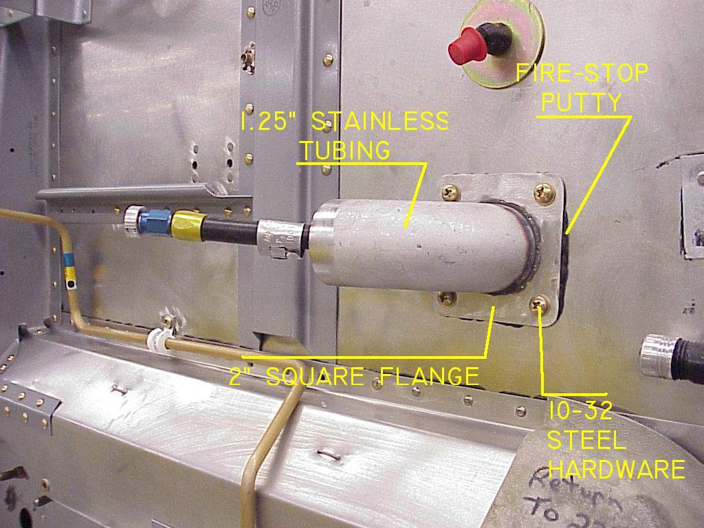
multiple, smaller fittings wouldn't work too . . . Here we see how a stainless weldment bolted to the firewall with steel hardware provides the structural component of a transition for wires and other relatively "soft" materials running between cockpit and engine compartment. Note generous flange area outside the tube to flange interface that is sealed with fire-stop when the flange is bolted into place. |
|
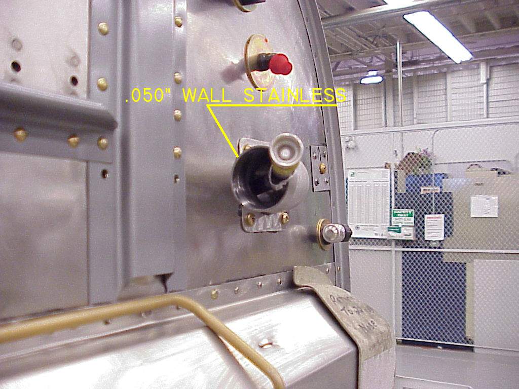
Click here for larger image The fittings
for this airplane are made from 0.050" stainless. Thickness and attaching
geometry are a function of how much support the fitting needs to provide for
the bundle of transitioning wires and tubes. The material shown here is pretty
hefty stuff and may have been selected as handier to weld than thinner material.
Drawings for other firewall fittings used in this same factory show materials
as thin as 0.020" thick. Builders can certainly experiment with thinner material and alternative joining techniques. Periodic inspections will show whether or not there are issues of mechanical robustness . . . not strong enough, they'll simply come apart. Given that fires are VERY rare, the failure of an experimental fitting doesn't represent a great threat as long as you do reasonably complete inspections during normal P/M activities . . . like every oil change. The worst thing that happens is that you have to build a more robust transition fitting and replace the broken one.
|
|
|
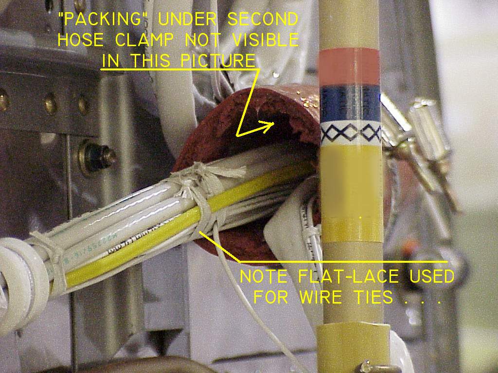
Click here for larger image Looking
up the business end of the finished transition. What's not visible in this
view is the packing placed around wires so that the second hose clamp
doesn't have to put a super-crush on the fire sleeve . . . . more on
this later.
|
|
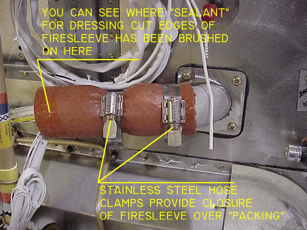
Click here for larger image The flight-ready
firewall penetration. A second hose clamp brings the fire sleeve down for
a snug fit on the wire bundle. A filler wrap around a wire bundle much
smaller than the i.d. of the fire sleeve makes for a better seal with
less crush under the second hose clamp . . .
|
|
|
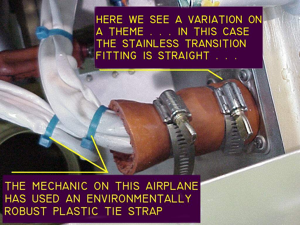
Click here for larger image On another
airplane, we find a similar technique except that the stainless steel
firewall fitting is straight, no 90-degree bend. Otherwise, installation and
functionality is same as shown above.
|
|
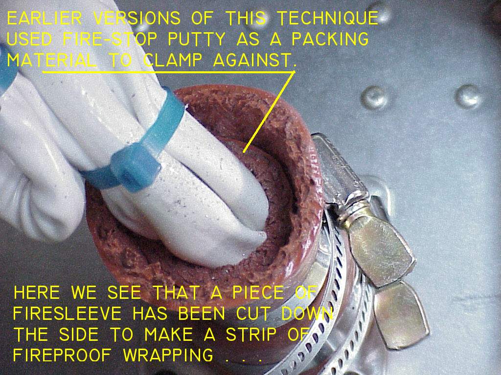
Click here for larger image This view
illustrates an interesting packing material used to build up the wire
bundle size. A piece of fire sleeve was cut down the side and made into
a strip of wrapping filler. Note that all exposed edges of the fire sleeve
are "doped" with the recommended sealer to preclude entry of moisture
and to keep the edges from fraying . . .
|
|
 Click here to contact Bob at AeroElectric Connection Click here to contact Bob at AeroElectric Connection |